Point motors
|
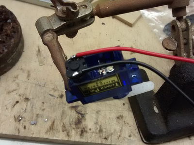
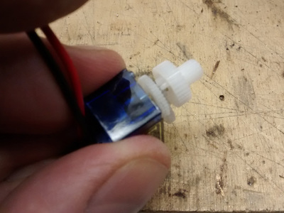
I wanted a quiet, slow motion motor rather than a solenoid. A friend gave me some Konrad units he'd bought and decided not to use. They are motor-driven, but at a voltage they can work reliably, clunk very noisily. We then discussed the use of radio control (r/c) servos and he provided articles on two methods - a) electronic, where the potentiometer based control is replicated by a simple circuit and b) where just the motor and gears are used in conjunction with micro switches.
The electronic version was tested first. It's based on a 555 chip and some other standard components. The motor is put into stall-mode at the end of the travel, but we devised a modification that used two push-to-make buttons and two pre-set pots to determine the end positions. Although it worked, and would be usable, there were glitches whereby it worked well in one direction and stuttered in reverse. Web searches showed this to be a common problem, but no solution was found. |
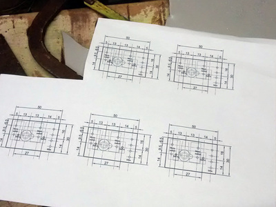
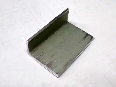
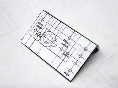
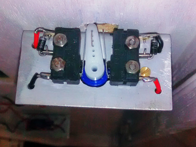
The mechanical version was then tried out. The supplied template was redrawn to suit the components sourced locally and also to tidy it it up bit. These were printed on plain paper and, once glued onto a piece of 3mm sheet bent into an angle, holes were drilled and the components fitted. A DPDT switch reverses the polarity, over-riding the diodes that come into play when the servo horn engages the micro switch arm. The unit was first tested on 3v and worked very well (video 1). A second, compact version was then made and tested on 1.5v (video 2). It was slower and a little quieter. Finally, both were run together on 1.5v and again, worked very well. A 1.5v power supply was then purchased for 99p (eBay/Hong Kong) so that the batteries can be dispensed with.
|
|
|
Video 1 shows the default design, as published in the MERG description. The servo is fitted vertically, which makes all of the fixings nice and simple. However, as the framing of the baseboard is shallower than the fixing plate, a modified layout was required. This was tested using 2 x AA batteries.
Video 2 shows the prototype compact version, where the servo is mounted sideways. This meant that some fixings overlapped with other components, so countersunk set screws were necessary. Whilst the unit worked, a fully symmetrical design was created for both of the final actuators. This was tested using a single AA battery. Video 3 shows the actuators fitted to the layout. The final connection to the point blade was made with 18" piano wire bent through the holes in the servo horns. This created enough play/tension for them to operate nicely. NB The Peco point springs were removed. By this time, the 1.5v power supply had arrived from Hong Kong. It was adjusted down to its minimum setting of 1.22v. The actuators were wired up in tandem, through a DPDT rotary switch. There's a clunk from the switch and whirring from the motors, but hopefully, these can be attenuated in due course. |
|
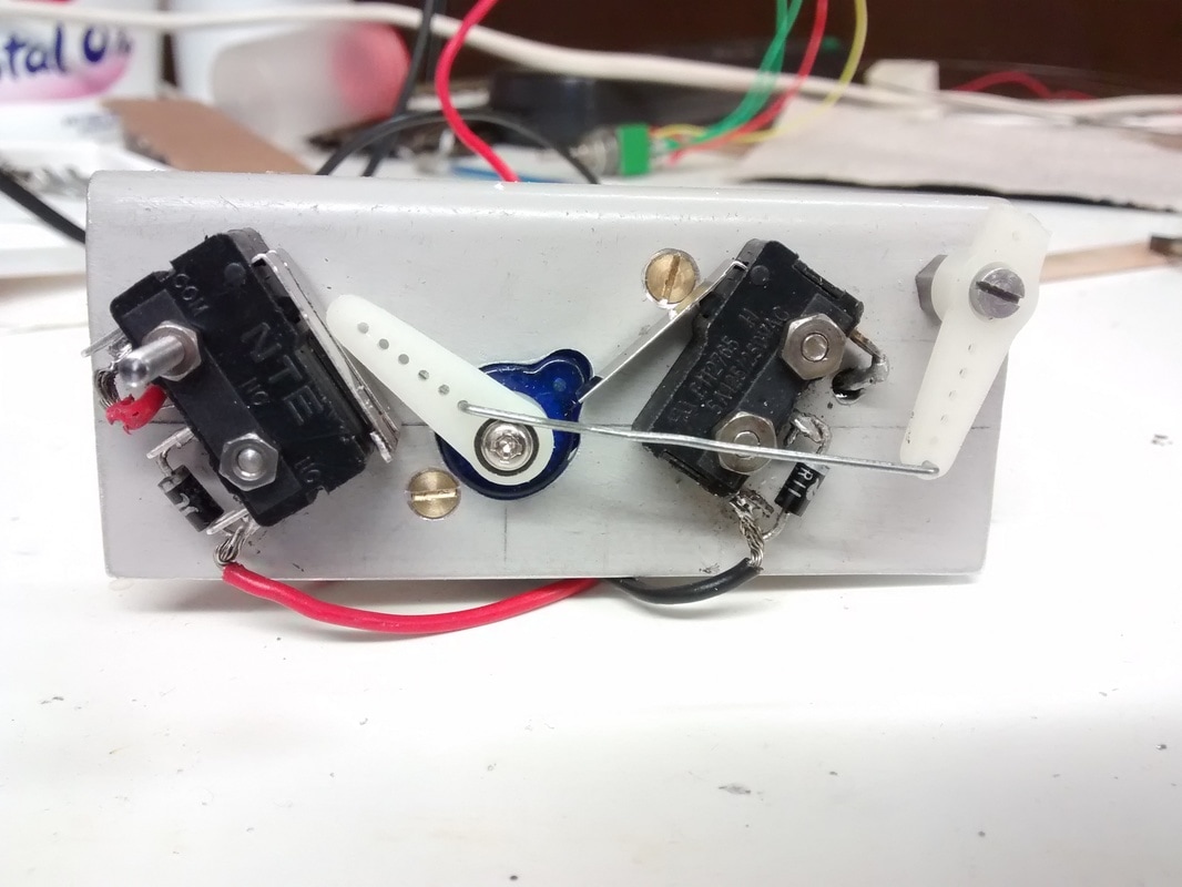
As we worked on the servo point motor on Worton Court, a better arrangement developed. The microswitches were moved apart so that the throw was greater, making it less susceptible to minor variations/inaccuracies in the setup. A second arm and linkage was introduced, increasing the power on the tie bar.
As the baseboard frame is only 34mm deep, the components had to be arranged to suit this depth. The tie-bar actuator wire (thin piano wire) is fitted onto the right-hand horn, passing through holes on both sides of the fixing bolt. The two actuators on BE were replaced with the new design. At the same time, the Peco set points were becoming a problem as the conductivity of certain parts became erratic. The points were replaced with hand-made versions with live frogs which required a switching mechanism. The microswitch on one side was 'doubled up' for this purpose. |

