Electrics
|
So, the time came to consider how all of the electrics would be brought together into a single location.
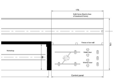
Speed/direction controller - still to be sourced, but it will probably have a knob and toggle switch, but could be on a 'wander lead' of fixed in a panel. Points - could use the rotary switch used for testing, or a DPDT toggle switch. Could also use simple momentary push switches. Workshop section - on/off toggle switch would be simplest. Doors (roller and hinged) - likely to require toggle switches. Could also use simple momentary push switches. The first design was for an extension board - half controller and half scenery. It would allow stock to be run beyond the workshop, onto the new section. The sketch below has just the switches and would require a speed controller on a wander lead. Construction started, but then another idea surfaced - infra red. I'd used an electronics kit from Maplin to control loco's on Belfield Quay and I still had one left. The kit comes with a mini control unit, but contact with the kit designer found that it used Sony coding, and a spare remote was sourced. These units have 2 analogue (up/down voltage using the volume/program buttons) and 6 digital (on/off). Using DPDT relays, the on/off's provide fwd/rev switching. (NB: The unit is still available from MUTR) |
Speed/direction controller - One analogue channel for speed and one on/off for direction.
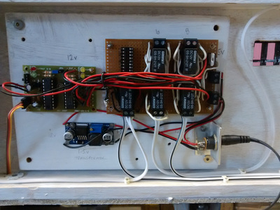
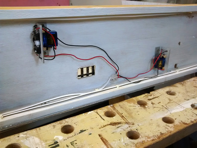
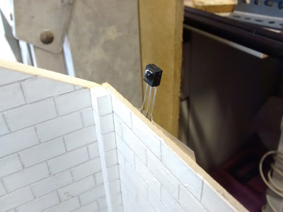
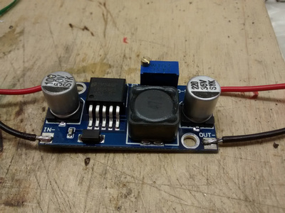
Points - One digital for polarity switching. Workshop section - One digital for on/off supply to the section track. Doors (roller and hinged) - One digital for polarity switching. This left one analogue and one digital channel spare! The kit was made up and configured for to control a 12v input (the unit itself works on 4.8 - 6v). The 1.5v supply could work on anything up to 30v so a single 12v supply would be ideal, with a 5v voltage regulator. The IR receiver was connected to a spare servo lead. Lots of relays, sockets, connectors and vero board were purchased from Bitsbox.co.uk. Some serious thought went into laying out the components, but it was all accommodated and the switching unit assembled and wired into the controller. The three units were fixed to a piece of painted 6mm MDF, together with a socket for the power supply. This was mounted under the left-end of the layout, partly as there was room, but also to allow the IR receiver to be mounted where an operator (at the workshop end) could easily direct the remote control. Finally, twin-core wire was used to connect the various relays to the track feeds, section and points. The door wiring can be added in due course. Everything worked, although the loco speed control was far more stepped than expected and will require some investigation. |
|
As the layout became used, a problem was discovered with the speed control side of the IR unit. Although there are potentially 250+ steps, there are only a handful in the voltage range required for slow running, which meant the 'steps' were very noticeable. Eventually, I purchased a dedicated controller - a Gaugemaster W - a hand held unit that worked perfectly.
|
However, this step could be the start of a process that leads to the abandonment of the IR unit as it probably wouldn't make sense to have two hand-held controllers. A return to a more traditional format along the lines of the small board described above wouldn't mean that everything has to go, as some of the relay switches could be retained. A trial period is obviously required. . .
|

